Roadbed
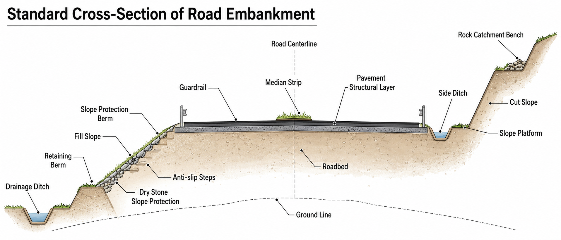
The labels in the diagram describe one working cross section. A roadbed is not just earth fill; it is the full system that ties the centerline, pavement structure, slopes, protection works, and drainage together.
| Term | Meaning | Design focus |
|---|---|---|
| Road centerline | The cross-section reference line tied to the horizontal and vertical alignment. | Lanes, median, roadbed width, and side slopes are laid out from it. |
| Median strip | The strip separating opposing traffic, often carrying planting, drainage, or safety elements. | Check width, drainage direction, and connection to pavement cross slope. |
| Pavement structural layer | The surface, base, and subbase layers that carry wheel loads. | Layer thickness and material control bearing capacity. |
| Roadbed | The earthwork body supporting the pavement structure. | Check compaction, width, settlement, and bonding to natural ground. |
| Ground line | The existing terrain before earthwork. | It determines fill, cut, or a mixed cut-fill section. |
| Fill slope | The outside slope of an embankment above existing ground. | Steeper slopes save space but need more stability checks. |
| Cut slope | The exposed slope created when the road cuts into terrain. | Slope ratio depends on soil, rock, weathering, and groundwater. |
| Slope platform | A bench inserted into a high slope. | Used for drainage, inspection, and reducing long-slope instability. |
| Slope protection berm | A transition strip near the slope toe or shoulder. | Leaves room for protection, maintenance, and drainage. |
| Dry stone slope protection | Stone facing placed on a slope to protect the surface. | Controls erosion and shallow movement, but does not replace slope stability. |
| Anti-slip steps | Steps cut into existing inclined ground before placing fill. | Helps new fill interlock with the original ground. |
| Retaining berm | A small earth or masonry berm at a slope toe or platform edge. | Controls shallow soil and water, but is not a full retaining wall. |
| Rock catchment bench | A bench at the toe of a cut slope for falling debris. | Keeps rockfall and loose material away from the carriageway. |
| Side ditch | A ditch beside the roadbed. | Collects pavement and slope runoff. |
| Drainage ditch | A ditch outside the immediate road edge or near slope toes/crests. | Intercepts and diverts water before it damages the roadbed. |
| Guardrail | A roadside or median safety barrier. | Used near high fills, sharp curves, bridge approaches, or fixed obstacles. |
Slope ratios below use vertical:horizontal = 1:m. A larger m means a flatter slope. Treat these as common design and editor defaults; real projects still need local standards, geotechnical checks, drainage, and protection design.
| Location | Common slope ratio or grade | Use note |
|---|---|---|
| Typical fill slope | 1:1.5 | Common default for compacted fill and low to moderate embankments. |
| High, weak, or wet fill | 1:1.75 to 1:2.0 | Use flatter slopes, benches, or protection for stability. |
| Typical soil cut slope | 1:1.0 to 1:1.5 | Looser or wetter soils should use flatter values. |
| Highly weathered rock or soft rock cut | 1:0.75 to 1:1.0 | Check joints, weathering, and rockfall risk. |
| Sound hard rock cut | 1:0.3 to 1:0.5 | May be steeper, but fractured zones still need protection. |
| Side ditch or drainage ditch side wall | 1:1.0 to 1:1.5; lined ditches may use about 1:0.5 | Unlined ditches should be flatter to reduce erosion and sloughing. |
| Slope platform cross fall | About 2% to 4% toward drainage | Platforms should drain to a ditch rather than hold water. |